Due to the high level of sophistication and complexity of today's Electronic Control Units (ECU) devices, special test methods are required. The idea of testing for system failures is not new, it is an important aspect of ECU validation and involves the introduction of electrical faults into a system (fault insertion testing). The test process typically duplicates various conditions which could occur because of corrosion, short/open circuits and other electrical failure inherited through age, damage or even faulty installation.
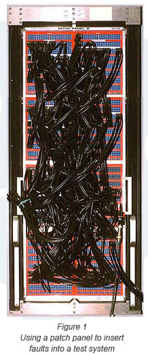
Typically, ECUs under development are exercised by a test system that simulates the device that the unit will control – this is sometimes called a Hardware-in-the-Loop (HIL) simulation. Stimulus instrumentation that simulates engine behavior, for example, is connected and controlled either by manual operation or by computer with measurement instrumentation used to capture analog and digital responses from the ECU. When it is necessary to inject faults, traditionally a patch panel, such as that shown in Figure 1, has often been used.
The various cables shown are used to connect any input/output (I/O) line of an ECU to stimulus or measurement instrumentation. The I/O lines may be manually disconnected to simulate an open-circuit or tied together to simulate short-circuits and the results measured. This type of solution has many inherent disadvantages, not least being size. There are also many hidden costs such as on-going maintenance issues, the need for significant knowledge on the part of the operator, potential human error and the cost of labor required to execute the test and record results.
Another major disadvantage of any manual method is the lack of repeatability. The ability to quickly reproduce a failed test condition is essential in a test system, either to aid development or to take corrective action. Being able to precisely reproduce the test procedure quickly is a major advantage in any upgrade or verification program.
The ability to gain software control of both instrument routing and the insertion of real-time electrical faults enhances both the testing process and the recording of the outcome. However, although a standard crosspoint matrix with an adequate specification is capable of handling the instrument routing to the device under test, the insertion of faults requires a specific switching architecture. |
|
 |