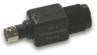
PP198衰减器能够让示波器测量喷油嘴和初级点火波形。
PP198衰减器是一个无源的20:1衰减器。这说明输入一个20V的信号,就输出1V的信号。因为信号被衰减,PP198衰减器可以让示波器测量电压高于其输入范围±20V。
当把PP198衰减器用于示波器测量感应信号例如喷油嘴和初级点火时,它提供增强的输入过载保护。千万不要把它用于次级点火测试。
The PP198 has been designed to allow fuel injector and primary ignition waveforms to be measured using PicoScope oscilloscope products. Please note this attenuator should not be used for any high voltage measurements other than fuel injectors and primary ignition.
The PP198 is a passive 20:1 attenuator. This means that a 20 V signal at its input will appear as a 1 V signal on the output. As the signal is attenuated, the PP198 allows voltages of up to 300 V to be measured (see the safety precautions).
The PP198, when used with Pico PC Oscilloscopes provides increased input protection against overloads when working with inductive signals such as injectors and primary ignition. Under no circumstances attempt to use this attenuator to measure secondary ignition (HT) waveforms, the PP178 Secondary Ignition Pickup lead should be used for this purpose.
How to Use the 20:1 Attenuator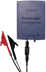
The PP198 connects in series between the oscilloscope and the test lead (right photograph). The PP198 is only suitable for use with an input channel ― it is not suitable for use with an external trigger input.
PicoScope can be configured to work with a 20:1 attenuator probe by selecting first the Settings menu and the the Probes menu. Select 20:1 attenuation for the channel the PP198 is plugged into.
| Specifications |
| Attenuation |
20:1 |
| Input Impedance |
1.053 MΩ |
| Input capacitance |
11 pF |
| Bandwidth |
10 MHz (-3 dB) |
| Max input |
300 V |
Safety Precautions
The PP198 is designed for measuring automotive signals such as fuel injector and primary ignition voltages (nominally 6, 12 or 24 volts). This attenuator must not be used to measure mains voltages or other hazardous voltages.
Fuel injector and primary ignition signals contain short duration high voltage spikes “inductive kicks”. We therefore recommend the use of two ground connections between the oscilloscope and the vehicle under test. One ground connection is made using the measurement test lead. A second ground lead should be connected between one of the BNC connectors on the oscilloscope and a secure ground point on the vehicle such as the negative terminal of the battery. Misconfiguration and/or failure to follow these warnings may cause damage to the product and/or computer and could cause injury to yourself or others.
其它汽车示波器附件 >>> |